INCA Main Window
The INCA main window visualizes the database structure and allows access to all items stored in the database. Furthermore, it provides handling functionality to configure, modify, set up, export and import data.
Within the main window you can open the
- Hardware Configuration Editor
- Experiment Environment
- Calibration Data Manager (CDM)
- Measure Data Analyzer (MDA)
Workspace
The Workspace combines all of the elements needed for a calibration or measuring session. The items named Dataset, Experiment Environment, and Hardware Configuration can be selected in the database. As a next step, they can be opened for configuration purposes in the respective editors.
Hardware Configuration Editor
The Hardware Configuration Editor comprises a software-based reproduction of the hardware that will be used for a specific measuring and calibration task.
A tree structure visualizes the interconnections between various modules, devices, and protocols. Several dialog boxes provide easy access to device and/or module parameterization, e.g., measuring channels on an ES650 Thermo & A/D Module.
Experiment Environment
The Experiment Environment provides the user interface for measuring and calibration activities.
The Experiment Environment user interface can be suitably configured to accommodate individual tasks. It facilitates the simultaneous handling of measuring and calibration tasks, and also supports concurrent access to multiple devices.
The following display elements are provided:
- Oscilloscope
- Numeric display
- Numeric editor
- Graphical editor
- Calibration scenario editor
In addition, multiple layers enable easy management of complex environments.
The experiment environment can be extended by own control and display elements. The example shows animated graphics (engine and instrument cluster) as well as slide controls and an animated road map.
Calibration Scenario Editor
The term calibration scenario describes the settings of a configurable set of calibration variables in the ECU. The Calibration Scenario Editor provides for the definition of calibration scenarios for several parameter sets, as well as their easy activation onboard the ECU. This makes it easy to compare alternative parameter settings of complex functions. Calibration scenarios can be saved and exchanged in the form of calibration data files.
The Calibration Scenario Editor also makes it possible to reset selected segments of characteristic curves and/or program maps to reference values. As an option, resetting the characteristic values can also reset the values of associated x-axis points. Selected parameters are displayed and calibrated in the appropriate editor.
Variable Selection Dialog Box and Experiment Configuration Editor
The Variable Selection Dialog displays all of the variables defined in the current environment, and allows an easy selection of a subset for the use within in the experiment. Multiple filter and sorting features, as well as the comfortable keyboard support, make selecting the right variables easier.
The sampling rate of the measurement variables can be set at the time of selection.
The Experiment Configuration Editor lists all of the variables used in the experiment and permits the modification of the respective parameter values. Custom display and control elements are integrated into the configuration editor by an open interface.
-
Video: Introduction to the INCA Variable Selection and Experiment Configuration Dialog Download
Memory Page Management Dialog
Calibration data and program code are stored onboard the ECU and in INCA in the form of memory pages. The data transfer between these pages, e. g. from PC to ECU, is handled by the Memory Page Management Dialog. The pages are represented by a small graphic, and the following actions may be chosen:
- Download to ECU
- Upload from ECU
- Copy from working page to reference page
- Programming flash memory onboard ECU or in ETK memory emulator
Calibration Data Manager (CDM)
The Calibration Data Manager provides functions for post processing of complete data sets or a subset of variables:
- List the content of a data set for documentation purposes in ASCII, HTML, or PDF format
- Compare calibration data from different sources and document the results
- Copy calibration data from one source data set into several others
- Export calibration data to CVX, DCM, PaCo, or CDF format
- Integration of customer-specific exchange formats via the ASAM-compliant intermediate format MSRSW V3.0
CDM works on a physical level, and thus overcomes project borders, even if data types and conversion formulas are different.
The Immediate Processing mode provides rapid access to calibration data and data comparison results.
Measure Data Analyzer (MDA)
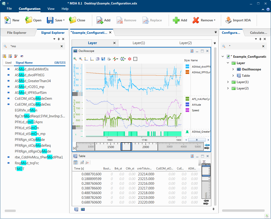
The MDA Measure Data Analyzer is used for the display and analysis of measurement data. The MDA provides graphical, tabular and statistical views. The MDA provides many useful features such as synchronous zooming and scrolling of display windows or searching for events.
For documentation, MDA provides for the printing of measure windows using a standardized layout and the export of measure data in MDF or ASCII format.
Integration with INCA:
- Automatic display of measurement data in the MDA, when a measurement is completed in INCA
- Display of snapshots during data recording with INCA
- Exchange of signal calculation formulas with INCA