The challenge to develop the powertrain of the future
Successfully mastering the testing and validation of fuel cell ECUs

To make mobility more sustainable, automakers are turning to battery-electric and fuel cell-based powertrains. To enable the efficient development and testing of fuel cell ECUs, innovative test and validation methods are required. ETAS delivers these in the form of a comprehensive package combined with simulation models.
The development of fuel cell-based powertrains is gaining attention and gathering momentum not only in the automotive industry, but also in government, especially among environmental policymakers. Particularly in the commercial automotive engineering sector (goods transport, public transport, etc.), fuel cell technology offers major advantages over purely battery-electric technology in terms of energy density, charging/refueling time, and so on.
To realize these advantages, however, fuel cells must continue to improve on a chemical, mechanical, and electrical level. Moreover, their electronic control with ECUs continues to pose challenges. Overcoming these challenges requires efficient test and validation methodologies targeted specifically at fuel cells.
Virtualization supports efficient software development
The primary goal of the HiL system setup is to simulate the driver, the vehicle, its components, and the environment as realistically as possible and necessary. The accuracy of the simulation can be defined based on quality metrics, which are set in close collaboration with the development teams involved in each particular project. Virtualization improves software development efficiency and reduces its time and cost. It does this by making major contributions to the progress of software development from the early pilot phase. With the HiL approach, safety-critical functions of ECU software such as hydrogen leak detection, safety concepts, and the activation and pre-charge algorithms of electrical components can be tested early on at the function developer’s desk. The resulting embedded controls software can be seamlessly transferred into the laboratory for parallel testing.
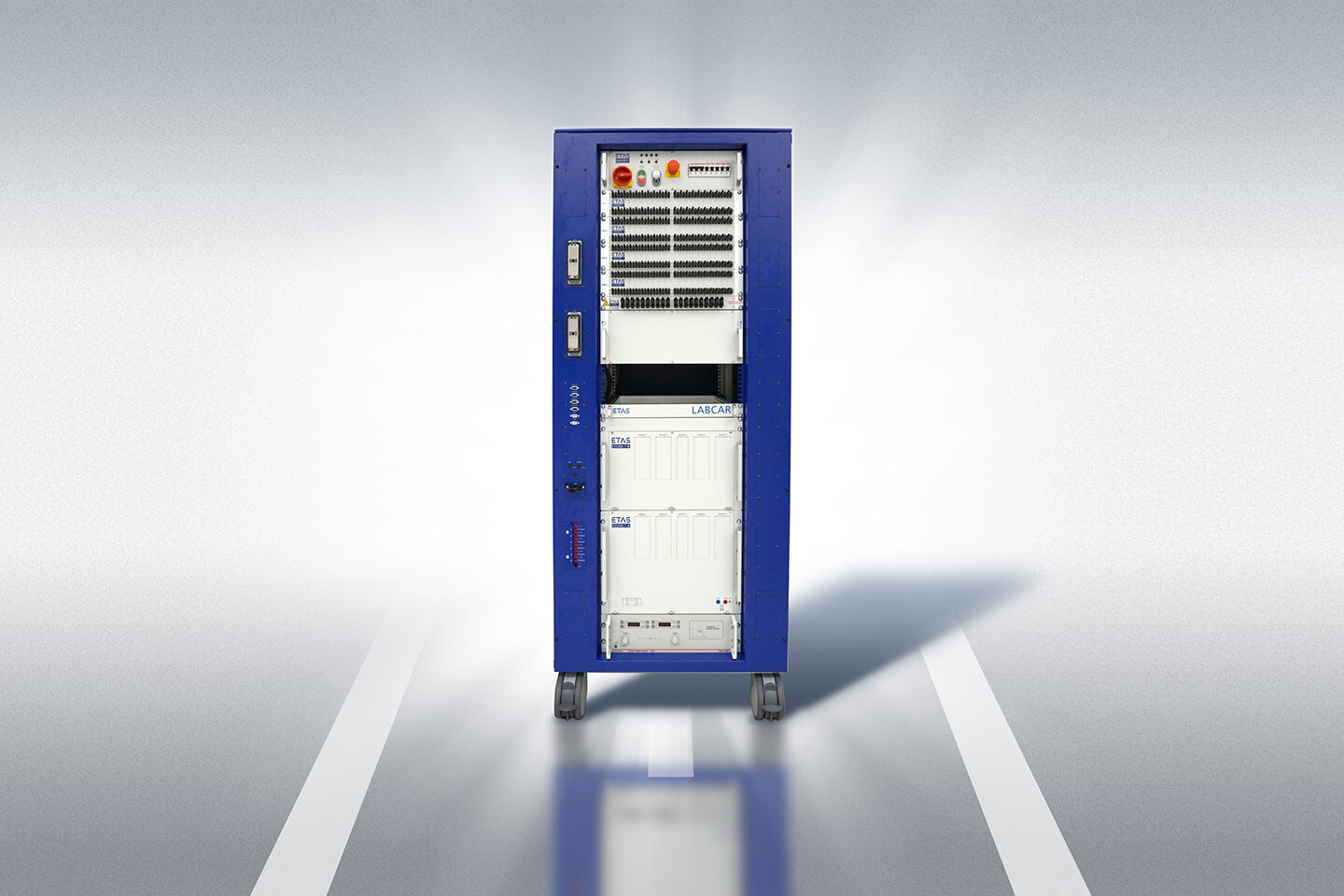
Fig. 1 shows the front view of a fuel cell HiL system. It provides analog and digital input/output hardware boards and bus communication interfaces (CAN, LIN, etc.) for configuration purposes. It also offers the option of incorporating real or simulated electronic loads for special functionalities. For example, a hydrogen-gas injector can be simulated with high accuracy using an electronic injector load module in the HiL system. The fuel cell model is designed for operation under strict real-time conditions on a real-time simulation computer. The software integration platform ETAS COSYM serves to connect the inputs and outputs of the physical fuel cell simulation model to the inputs and outputs of the HiL hardware. The fuel cell ECU calibration interface closes the loop between simulation, fuel cell software interaction, and the simulated fuel cell system.
Based on an exact physical simulation model
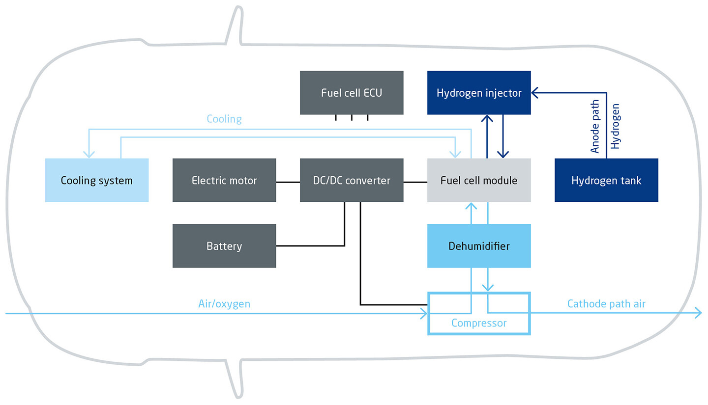
The core component of the HiL system is the physical simulation model of the fuel cell system ETAS LABCAR-MODEL-FC. This consists of five main parts (Fig. 2) that have a significant influence on the efficiency of the fuel cell system:
- Fuel cell module
- Anode path with hydrogen supply/tank
- Cathode path for the air supply
- Cooling for system temperature control
- Electrical high-voltage path for energy storage, voltage conversion, and electrical load (electric motor)
In order to run this simulation model on the HiL system, some important conditions must be met. For one, the software model must be executable in real time.Furthermore, the single-cell fuel cell model must be capable of precisely simulating physical laws, such as losses and other effects that influence electric current, temperature, and electrical resistance stoichiometry.
A detailed water composition and a two-phase water model calculation are also required to represent the motion and states of aggregation of water in the gas channel. Equally important in this context is the ability to specify the individual gas composition of each electrode and describe pressure loss characteristics. A 1D multicomponent gas channel model can be used for this purpose. Moreover, support is required for a variety of flow field designs and the detailed calculation of internal cell humidity.
In addition to these basic functions, a highly accurate and precise simulation of cold start behavior in fuel cell operation is also necessary. This requires a membrane temperature model as well as the incorporation of non-linear dynamics of the cell water composition and temperature-dependent fluid properties. Ideally, a model library would also be implemented to enable use of the simulation model on a variety of fuel cell architectures.
Practical implementation
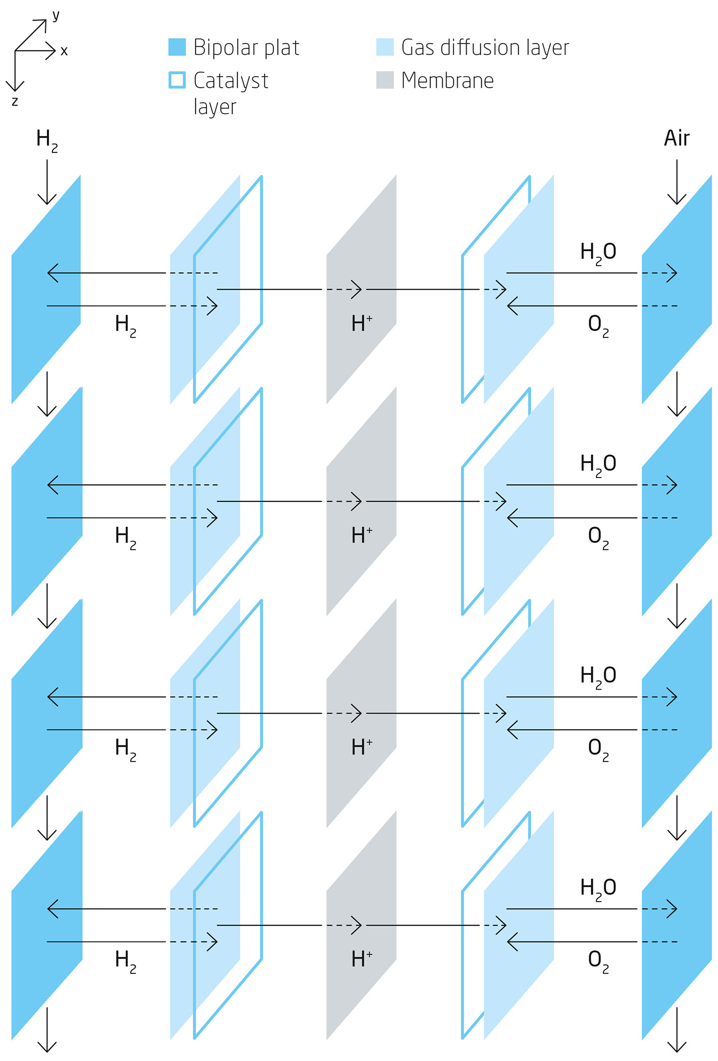
ETAS has systematically put these requirements into practice. As shown in Fig. 3, individual fuel cells can be separated into multiple segments along the gas channel. While the Z coordinate follows the gas flow, the X and Y coordinates are arranged perpendicular to the membrane and gas channel. Each segment addresses all the functional layers of the fuel cell, including bipolar plates, gas channels, gas diffusion, and membrane. The same system of equations can therefore be used for both individual segments and an entire cell. Mass and heat flows connect the segments and layers of the cell. Exchange between model segments only takes place via heat and mass exchange in the gas channel and bipolar plates.
By contrast, the membrane electrode arrangement (MEA) hardly contributes at all to the energy exchange with adjacent segments. Furthermore, its expansion in the X direction is in orders of magnitude smaller than in the Z/Y direction. Spatial pressure and concentration gradients – which drive proton and water transport through the cell – therefore occur primarily in the X direction. To model the spatial characteristics, it is sufficient to focus on the gas channel and bipolar plates. This kind of MEA model can be evaluated segment by segment and is not directly influenced by the 1D model.
The ETAS approach is rounded out with a library of components including the hydrogen gas injector, hydrogen recirculation blower, vent valve in the anode path, air compressor and humidifier in the cathode path, cooling pump, MCV valve in the cooling path, safety circuit, and DC-DC high-voltage input. The result is a complete fuel cell plant model for use in the HiL system.
Application
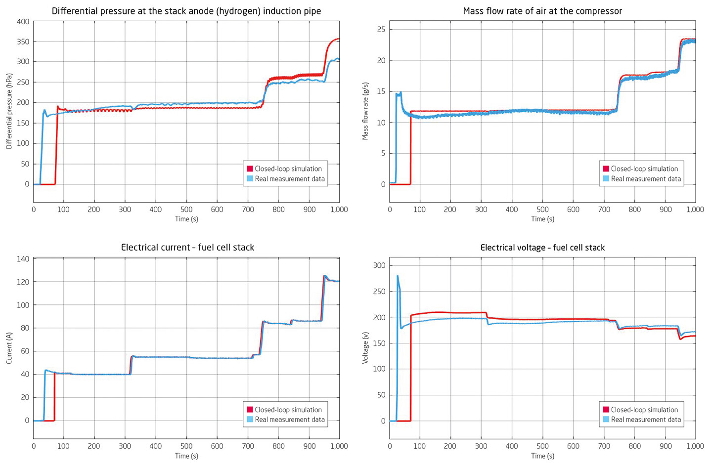
The performance and precision of the ETAS solution is illustrated by a comparison between the results of an uncalibrated real-time LABCAR HiL simulation platform (Figure 4, red line) and a vehicle test-drive (blue) using the same fuel cell ECU. The anode (hydrogen) differential pressure follows much the same path as in the vehicle test-drive. The mass flow rate of “air” at the compressor also sees a largely equivalent trend between the test run and model. Moreover, the electric current and electrical voltage delivered by the fuel cell also exhibit close correspondence between the model and vehicle data.
Yet this solution offers still more potential. The accuracy of the simulation can be optimized further by calibrating the fuel cell model in advance using test bench measurements, for example with ETAS ASCMO-MOCA. Currently, the fuel cell model offers the ability to set some 350 parameters for this purpose, thereby giving developers the flexibility to cater to the requirements of a variety of ECU software projects. They can also improve the simulation results further by integrating additional simulations of the electric motor, battery, or vehicle dynamics.
The fuel cell model can be deployed not only for test and validation on the HiL system, but for example also for virtual test runs in the early phases of software development. The ETAS COSYM XiL test platform allows the software functions to be validated in a closed-loop experiment while also enabling the simulation model to be integrated into a higher-level vehicle model that is also simulated. By simulating all the vehicle buses – such as virtual CAN and Automotive Ethernet networks – developers can achieve a realistic analysis of network communication even at this early stage of development.
Summary
Safety, performance, and monitoring of powertrain components will continue to be important parameters for the development of electrified powertrain components in the future. For the development and refinement of fuel cell ECUs in particular, precise, real-time simulation of the fuel cell provides the basis for validation on the HiL test bench. Furthermore, the use of SiL test platforms enables concurrent tests to be performed even at an early stage of development. The XiL solution from ETAS presented here – together with the simulation models – provides the basis for highly efficient development of fuel cell ECUs in accordance with all safety requirements. It brings the fuel cell one step closer to being incorporated in the large scale series production of tomorrow’s climate-friendly vehicles.
Authors
Frank Ruschmeier is Application Field Manager Test and Validation at ETAS Automotive Technology Co., Ltd.
Chaoyong Tang is Program Manager Test and Validation Fuel Cell at ETAS Automotive Technology Co., Ltd.
Raphael Hans is Test und Validation Modeling Specialist and Fuel Cell Expert at ETAS GmbH.
Further information
LABCAR-MODEL
-
 The challenge to develop the powertrain of the future Download