XCP – AUTOSAR single pointer method via XCP protocol
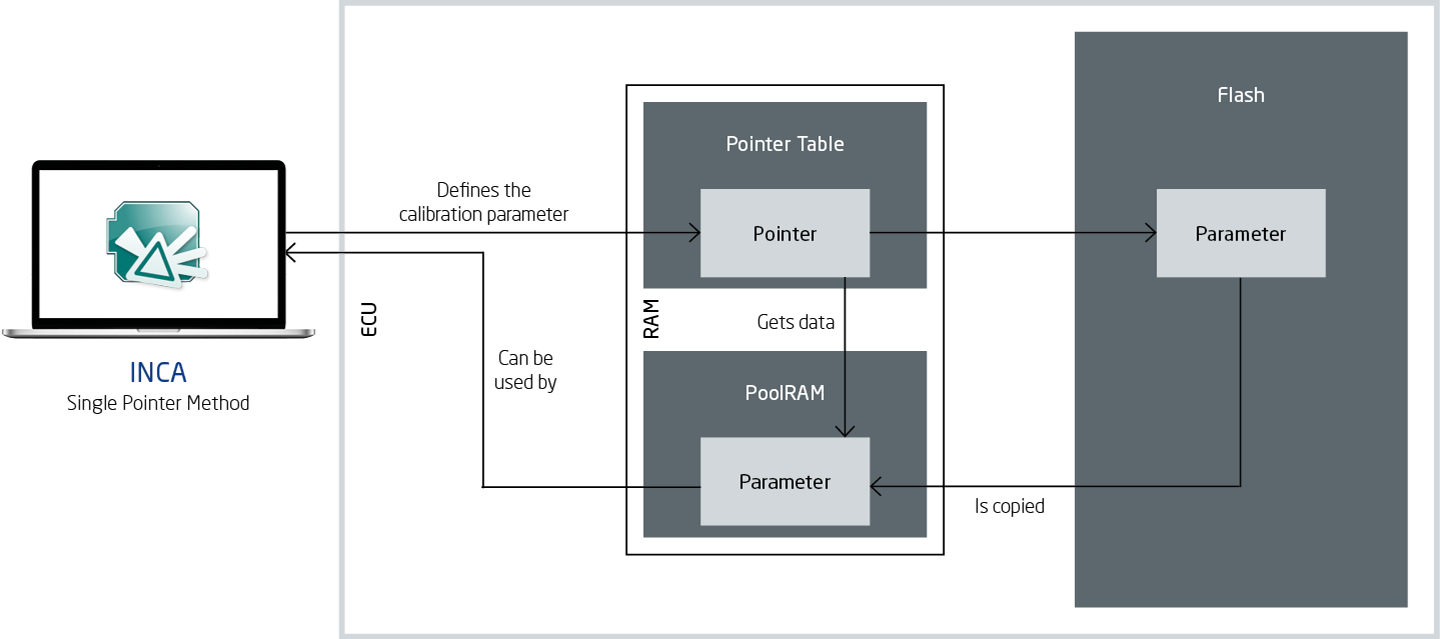
With the calibration concepts of the AUTOSAR single pointer method (SPM), version 7.2 SP14 enables INCA to emulate calibration data dynamically on working pages. The parameters or groups of parameters are defined in the A2L file and are made accessible by the controller via the pointer table. The pointer table is located in the random access memory (RAM). Internal controller algorithms also use the pointer table to read parameter values.
A distinction is made between two pointer tables that are both in the RAM memory: While in the case of the original pointer table each pointer points to a parameter in the flash memory, each pointer of the working page either points to the flash or working page memory.
This approach makes calibrating with the limited emulation RAM possible, without the need to flash. The number and size of the groups is flexible so that different applications are supported. All information needed to support this calibration concept is part of the A2L file.
AUTOSAR – File reparsing
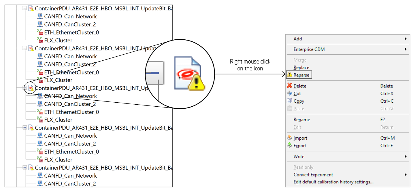
As of version 7.2 SP14, INCA displays the status of the AUTOSAR elements in the database objects list box. A yellow warning symbol on the AUTOSAR container icon indicates that the data from the current converter has not been converted. The user can therefore see which elements still have to be converted manually before INCA can use them. Implicit reparsing occurs when a used workspace uses such an AUTOSAR element – for example to open an experiment. In this case, reparsing takes place automatically. Explicit reparsing for a specific AUTOSAR data entry can be started via the context selection menu.
Calibration data manager (CDM) – Multiple column view
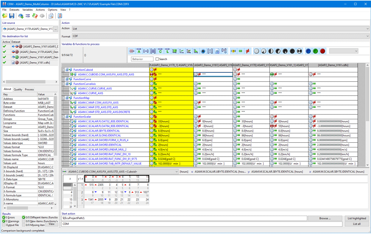
To display the source date, INCA 7.2 SP14 allows you to switch between a single and multiple column view in the calibration data manager. For certain types of data such as ARRAY, ASCII, or Boolean, differences between already compared datasets can hereby be made visible. Each dataset therefore has its own column whereby the background of the source dataset is yellow.
The target dataset shows a single quick comparison with the source dataset. The source dataset shows a quick comparison of all datasets. An equal sign with an asterisk indicates that the target and source values are equal across all datasets. A not equal sign with an asterisk indicates that the target and source values are not equal in all datasets. A not equal sign with the number 1 indicates that the source and target datasets differ in precisely one dataset.
Inline compare (see INCA 7.2 SP11) allows individual values of the source and target dataset to be compared. Either functions or groups can be compared with each other here. The comparison is not limited to a certain number of datasets.
Data type – Supporting 64-bit integer data types
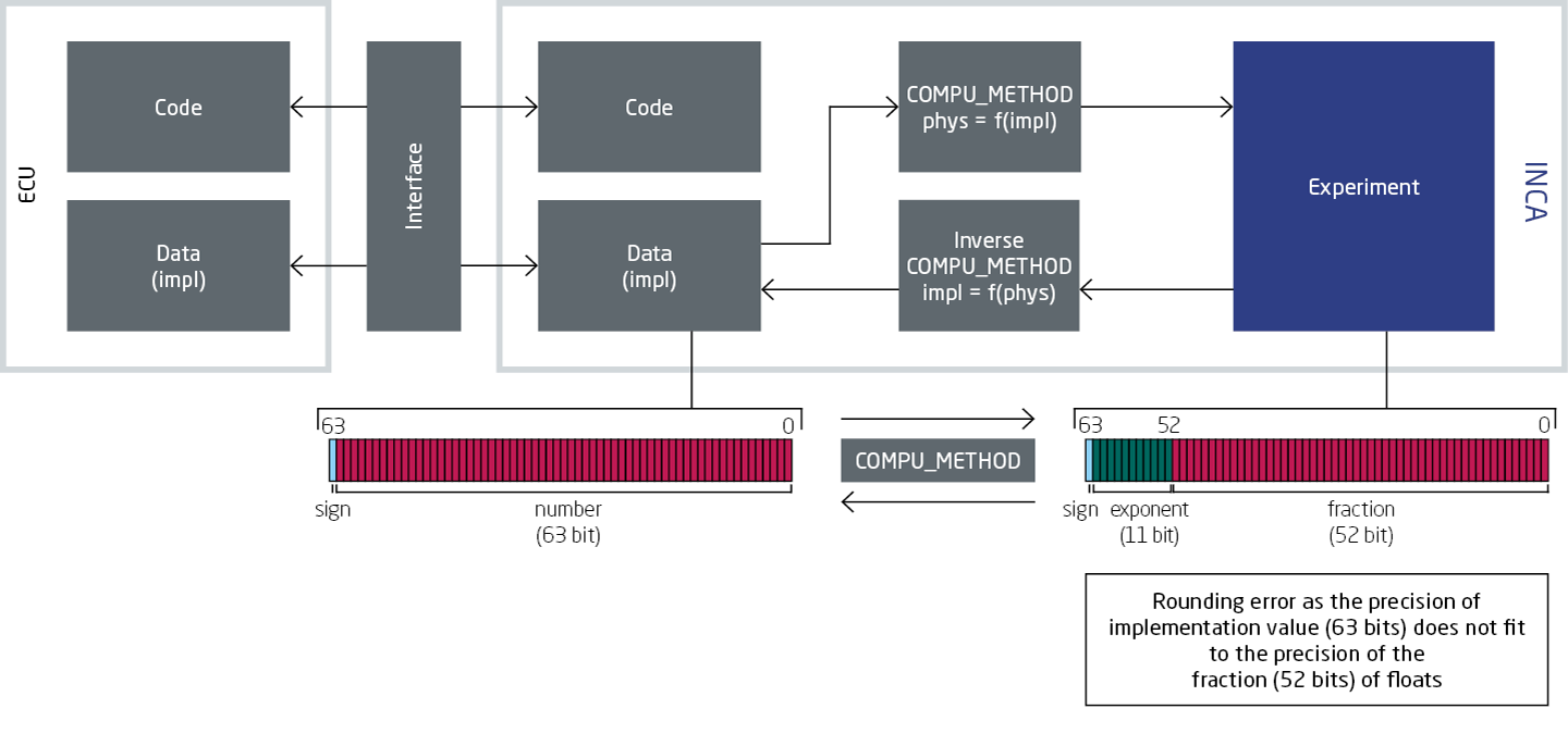
INCA 7.2 SP14 also supports 64-bit integer data types for variables implemented in the controller. The physical value is hereby limited to the precision of a floating-point number with a mantissa of 52 bits. INCA therefore displays the integer values that exceed 52 bits only as implementation values.
In the combined editor, it is possible to switch back to the display of the physical number, as long as it is presentable (limited to 52 bits for floating-point number).
XCP – Additional setting for the UDP source port in INCA
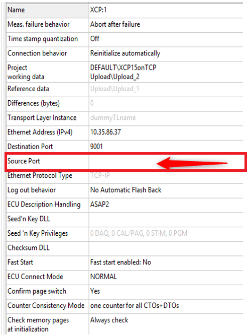
For the XCP-on-Ethernet protocol-based communication, INCA 7.2 SP14 allows a specific UDP source port to be specified. It can now be entered in the hardware configuration window (HWC window) as a value. For the XCP resume mode for UDP, it is essential that the XCP master can assign the source in order to detect the incoming frames.
For standard behavior, this parameter is blank, which means that INCA is using a random source port. If the user configures a specific source port, INCA will use this one as the communication parameter.
INCA-SIP – Remote control
INCA 7.2 SP14 allows you to have both a calibration and a simulation PC with INCA-SIP (Simulink® Integration Package). The remote control function therefore allows you to connect a computer to a different INCA instance by means of INCA-SIP. DCOM is used here to remotely control INCA from INCA-SIP. A configuration is needed here that permits DCOM. INCA and INCA-SIP respectively must be installed on both computers to ensure that all the necessary components can be found on each machine.
A2L and S19 files are stored on a shared network path. Both computers require access to this directory location; the directory can be on a local or network drive.
INCA-SIP – Allow "Connect to INCA" while the model is running
INCA 7.2 SP14 allows users to connect to a model via INCA-SIP even if it is already running or if it is stopped. In order to do this, there must be an INCA-SIP block in the model and in INCA in the tools menu, under menu item INCA-SIP, the option "Connect to INCA" must be selected.
Controller and configuration settings can be changed when the model is running. These changes take effect the next time a connection is established.
If the model is not recompiled at the time of reconnection, quicker reconnection speeds are achieved.
Measurement recording in INCA EE – New user dialog in MDA V8
If during a measurement recording in INCA EE the MDA V8 is started with INCA 7.2 SP14, then there is a new user dialog. It opens if there is already a measurement file in MDA V8 and INCA does not send an XDA description. The prerequisite however is that MDA V8 is open and the MDA configurator is active. If however the MDA configurator already contains one measurement file, then it is replaced.