With INCA, ETAS offers a flexible family of software products for calibration, diagnostics, and validation of automotive electronic systems. It comprises all functions required by development, calibration, and test engineers to validate, adapt, and debug ECU application software. INCA is easy to use and offers user-oriented interfaces available in English, German, French, Chinese, or Japanese.
INCA is used throughout the development process from the initial calibration of a function model to the pre-calibration of an ECU at the test bench, to the final optimization in the vehicle. It is deployed at the desk, in the lab, at the test bench, and in the vehicle. Applications range from PC simulations to vehicle instrumentation and from offline management of calibration data to measurement analysis.
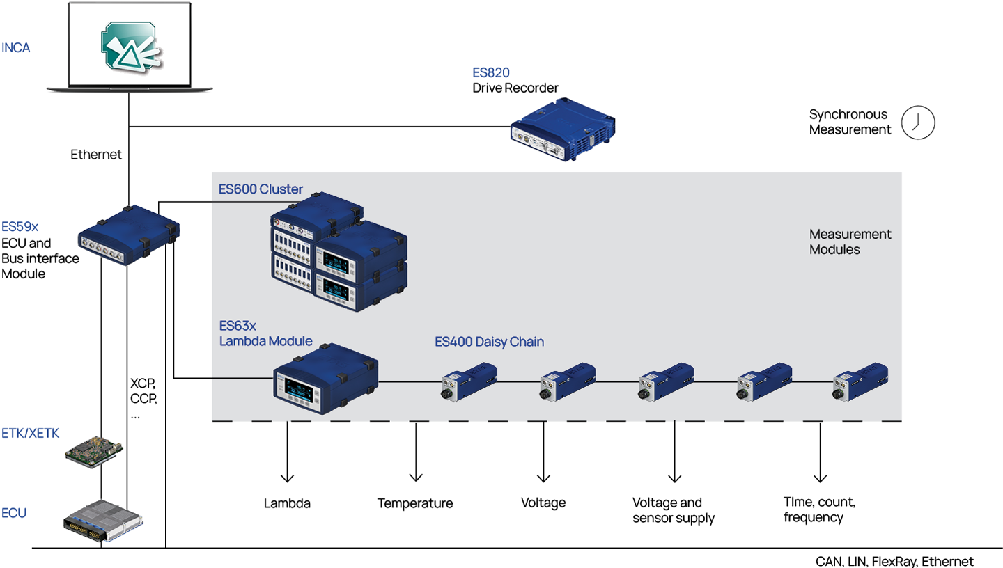
INCA supports the full line of ETAS compact hardware modules and the powerful ETK, FETK, and XETK ECU interfaces in measurement, prototyping, calibration, and diagnostic applications. For effortless integration into different environments, INCA offers a wide range of open and standardized interfaces.

Measurement and ECU Calibration
INCA facilitates the adjustment of function parameters, maps, and tables either offline or during ECU runtime. In the course of this, the tool manages the ECU’s volatile and non-volatile data memory and resolves parameter dependencies. Powerful editors display scalars, curves, or maps as tables or graphs in physical or hexadecimal format. Calibration scenarios embrace multiple parameter values of specific functions and ease the comparison of different settings.
For offline management of calibration data, INCA offers sophisticated functions for listing, comparing and merging datasets. In addition, INCA supports processing of meta data describing the history and maturity of a parameter or function calibration with the INCA-QM-BASIC (Basic Quality and Maturity Tracking) add-on.
In parallel to calibration, INCA provides for the acquisition of data from the ECU and vehicle busses such as CAN, LIN, Ethernet, and FlexRay. In addition, INCA measures signals from sensors and the vehicle environment. Quantities derived from measurements and calibration variables can be calculated and displayed online. Data recording with several independent recorders may be started and stopped by sophisticated trigger conditions. Parallel recording of data related to different trigger conditions is possible. Data records comprise measured and calculated signals, calibration parameters, trigger options as well as user comments.
With ODX-LINK, INCA offers an ODX-based solution for validating vehicle diagnostics and ECU programming.

Diagnostics
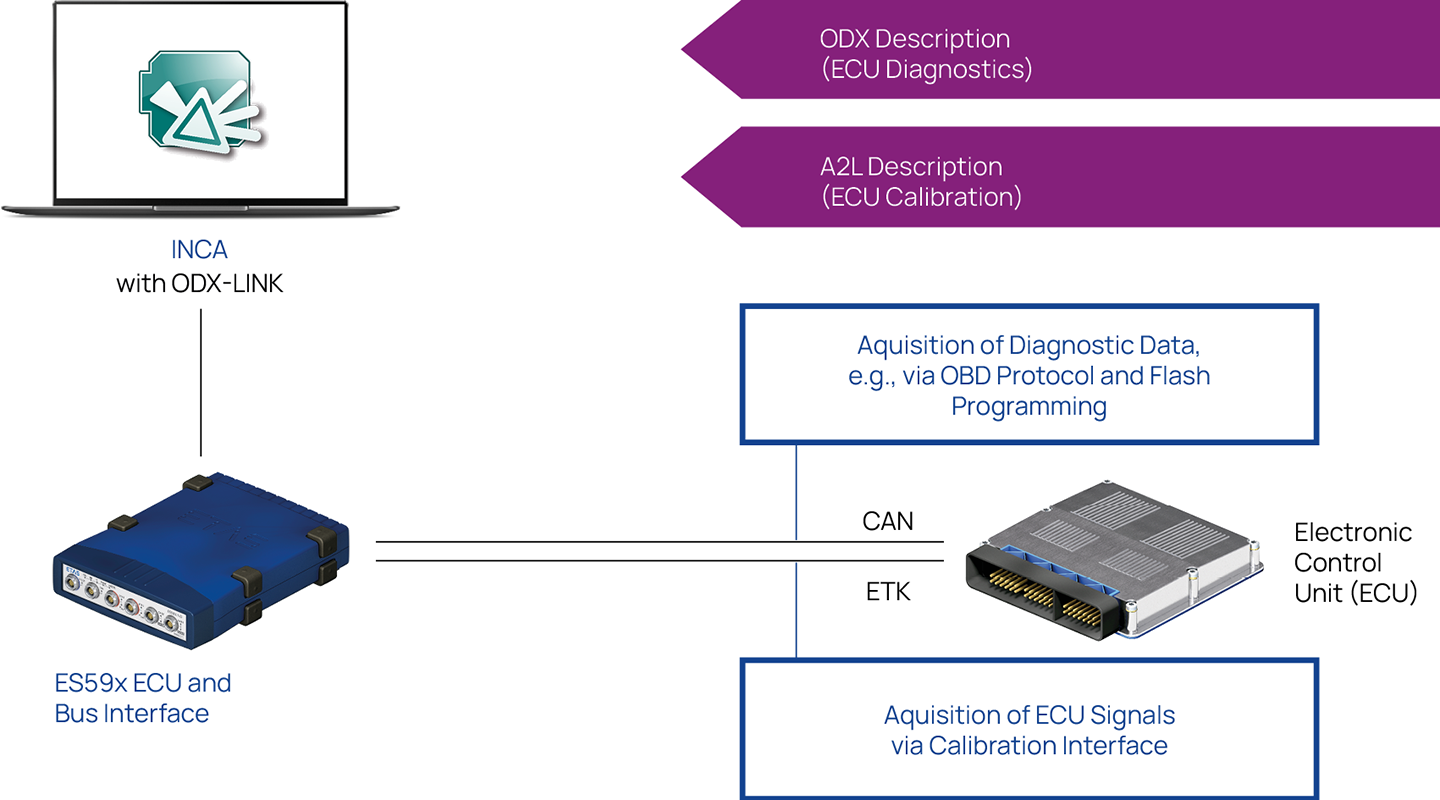
ODX-LINK adds ECU diagnostics capabilities to the measurement and calibration functionality of the INCA basic product.
INCA/ODX-LINK acquires calibration and diagnostics related signals in parallel. Both types of signals can be used for triggering and calculation of derived signals in the same manner. All data is recorded in one measurement file and displayed in the same views. A single ECU and bus interface module can provide connections for both ECU diagnostics and calibration.
ODX-LINK integrates scan tool functions based on diagnostic services required by OBD emission regulations. Based on the services defined by ISO 15031-5 and SAE J1979 only, the easy to use OBD scan tool visualizes fault memory entries, status information of monitoring functions, vehicle information, in-use monitor performance ratios, and environmental data known as freeze frames.
Beyond OBD, ODX-LINK facilitates full diagnostics of ECUs compliant to the ODX standard. In addition, INCA can emulate a service tester and execute troubleshooting functions. In this way, service diagnostics can be validated long before service tester hardware is available. By including a remote-operable ODX-FLASH tool, INCA/ODX-LINK provides a complete solution for validating ODX-based vehicle diagnostics and ECU reprogramming.
Measure Data Analysis
In the ECU development process, measurement data relating to different variants of calibration parameter values must be compared. The MDA measure data analyzer is used to visualize, post process, analyze, and document measurements. It provides for evaluating the correlation of diagnostic data with signals from the ECU, sensors and vehicle busses. By use of predefined configurations, measurements can be displayed in a consistent manner. By using the same views and settings for the same signals independent of the individual record, similar measurements can be easily checked against each other. MDA print layouts can be adapted to any corporate design, enabling professionally looking documentation of the measurement results.
While simulating, prototyping, or testing functions, measurement data often serve as stimuli. MDA is used to select and prepare stimuli signals from raw measurement data which was recorded at the test bench or in the vehicle. MDA is capable to process large amounts of measurement data. It supports the MDF file format, an ASAM standard which is commonly used by development and test tools.
Measurement and Calibration at the Test Bench
For integration with test bench automation systems, INCA supports the established ASAM interfaces, i.e., the ASAP3 protocol and the ASAM MCD-3 MC object model. The calibration cycle times that can be realized with these standard interfaces are well suited for steady state experiments.
Rapid measurement and calibration methods are supported by the INCA-MCE Measurement and Calibration Embedded add-on to INCA. By providing real time connection of the test bench automation tool to the ECU, INCA-MCE provides for outstanding measurement and calibration performance.
INCA-MCE runs on the ES910 module serving as real time ECU interface. Either the standard EtherCAT or the application specific iLinkRT Ethernet real time protocol is employed to connect ES910 with the test bench. Using these protocols, the automation tool and INCA-MCE exchange measurement and calibration parameters as physical values addressed by name. To communicate with the ECU, INCA-MCE transforms all data into the appropriate binary values and memory addresses.

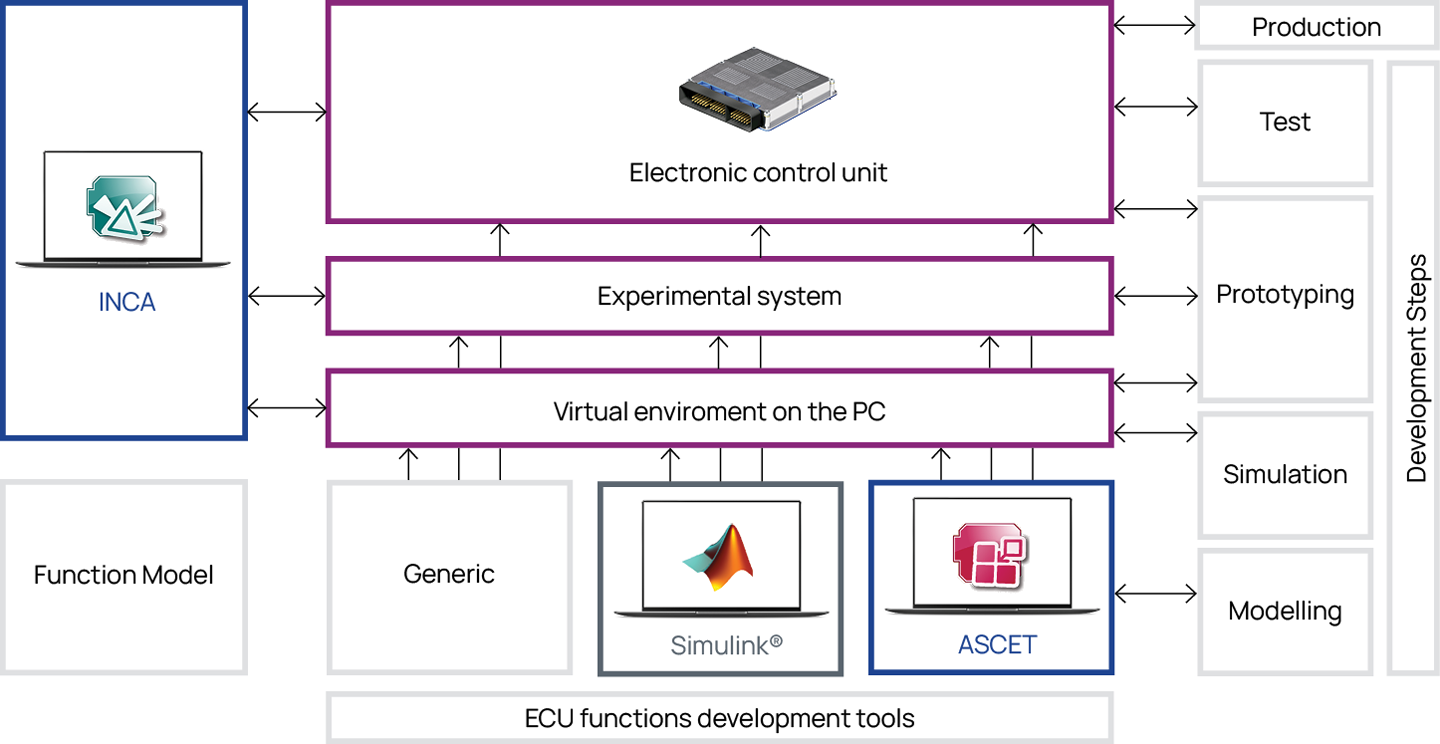
The comprehensive measurement and calibration capabilities of INCA can be most beneficially employed in PC simulation and prototyping applications. Simulating the behavior of new software functions in a modeling environment on the PC is an established development method. Prototypes are used to validate new functions in a real environment.
Function prototypes can be implemented on different targets. As required, they may be executed on an ECU, an experimental system, or a PC. Regardless of the simulation or prototyping environment that is employed, INCA provides add-ons that establish measurement and calibration access. INCA connects to generic simulation environments on the PC using the XCP protocol over TCP/IP connection. INCA-SIP links INCA with Simulink®. ETAS’ INTECRIO facilitates integration of generic C code, Simulink and ASCET models within one prototype. INCA-EIP provides full access to INTECRIO prototypes running on the PC and to INTECRIO or pure ASCET prototypes implemented on an experimental system. By using the same INCA tool at each step, calibration values can be easily refined.

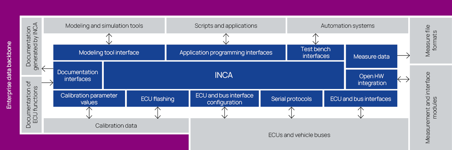
In addition to automation system interfaces, the tools of the INCA product family provide a wide range of open and standardized interfaces for configuration, data exchange, documentation, automation, and integration with customer applications.
ECU access is configured by using description files in A2L and ODX format as defined by the ASAM MCD-2 standards. Bus communication on FlexRay, CAN, and LIN is described in the respective FIBEX, CANdb, LDF, or AUTOSAR format. Calibration data is stored in hex formats, while several ASCII formats are supported to exchange subsets of calibration parameters. Measure data is recorded in MDF files. Being a de-facto standard in automotive testing, the binary MDF measurement data format is supported by commonly used data evaluation tools such as MATLAB® and FAMOS.
INCA provides parameter listings and the results of calibration data in XML-format. The configuration of experiments and connected hardware also can be documented in XML-files. To provide for interactive access of parameter and function model descriptions within INCA, an open interface facilitates integration of electronic ECU documentation in PDF or Windows® Help HTML format by the customer.
For tool integration, INCA offers application programming interfaces (APIs). The COM-API is based on the Microsoft COM (Component Object Model) standard. COM-API facilitates remote control of almost all INCA functions and provides maximum flexibility. Using INCA-MIP, MATLAB® scripts can be employed to automate or semi-automate calibration procedures. Manual input provided to the scripts by INCA-MIP can be combined with numerical calculation and optimization routines that utilize the rich MATLAB® libraries and toolboxes.
The programming interface INCA-INS.DK allows users to develop own display windows for measurements and calibration parameters and to integrate them into the experiment environment of INCA.