At a Glance
- Provision for fast handling of large ECU projects
- Exploitation of the full computing power of multi-core PCs
- New, high-performance oscilloscope with extended display options
- Comparing of calibration data concurrently with ongoing experiment
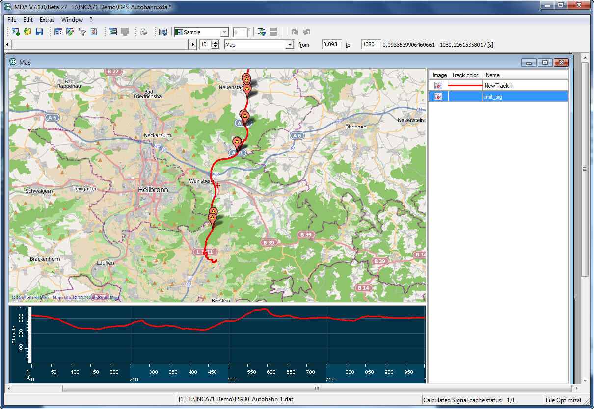
- Graphical display of test track routes in the Measured Data Analyzer (MDA) based on GPS data
- Simultaneous utilization of several rapid prototyping modules by INCA-EIP
- Support of the ETAS compact hardware modules ES415 and ES930
ETAS INCA is the first choice worldwide for the majority of measurement and calibration tasks. The new version INCA V7.1 of the Integrated Measurement, ECU Calibration and Diagnostic Environment by ETAS makes quick work of day-to-day tasks – even with the most complex control systems.
INCA V7.1 comes with enhanced system performance; with INCA V7.1, even ECU projects featuring high amounts of measurements and calibration parameters can be quickly handled by the user. Large experiments open decidedly faster. Plus, opening and working with the variable selection dialog has been noticeably expedited.
When acquiring data, INCA V7.1 utilizes all available processor kernels of a multi-core PC. The display of the new INCA oscilloscope is handled by the PC’s graphics adapter, which unburdens the main processor. During recording it is possible to index measurement files, making opening and working with the respective data in the MDA quite a bit faster.
Experimentation in relaxing comfort
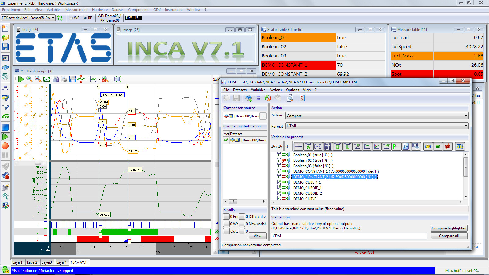
Integrated into the experiment environment of INCA V7.1, the new oscilloscope makes it possible to dissect the display of analog measurement values into several horizontal strips, enabling vertical stacking of the display with a variety of signal groups. And because dynamic axes automatically adapt to the current measured values, the oscilloscope always shows the entire measurement range.
To analyze measurement data, the oscilloscope’s display can be stopped and scrolled back during an ongoing measurement session. In this way, cursors aid in the quick evaluation of already acquired measurement values. Upon leaving the analysis mode, the current measurement values are again automatically displayed.
INCA V7.1 enables the user to simultaneously open both the experiment environment and calibration data manager (CDM) to compare current calibration data in CDM with the data from the reference page. A similar action is available for comparing and copying several sets of working data in CDM concurrently with the open experiment environment.
Furthermore, with INCA V7.1 it is now also possible to display − in addition to the measurement variables − groups of parameter values with color highlights. As a space saving measure in the experiment environment, the display of physical units of measure can now be toggled on and off in measurement and calibration tables.
New hardware options
INCA V7.1 supports a number of new hardware modules supplied by both ETAS and third-party vendors. Examples of this versatile integration are the new ETAS ES930 Multi-I/O Module, which offers an entire range of different analog and digital inputs and outputs and the new four channel ES415 module which can capture analog date with 100 kHz.
The CAN interfaces support various devices by Kvaser, as well as new modules from Vector Informatik.
Visualization of GPS data in the Measured Data Analyzer
A new feature of the Measured Data Analyzer (MDA) consists of a display of GPS data. It inserts test track routes into a roadmap. To this end, license-free OpenStreetMap files are used. The documentation of measurements was extended through the addition of information about the measurement hardware and the firmware version being used. INCA stores this information in the MDF4 measurement files so that it can subsequently be displayed in the MDA.
In addition, the new MDA presents a number of improvements benefiting user control. In the tool options for example, the oscilloscope display of event traces can be toggled on and off and a standard increment can be entered for navigation with the analysis cursor.
Standards conformity
INCA V7.1 supports the Fibex V3.1.1 and XCP V1.1 versions of the standards for the description of vehicle buses and the communication with ECUs. In terms of CAN monitoring, INCA now also supports AUTOSAR system configuration templates V3.1 and V3.2, in addition to DBC files. The use of the ASAM MCD-2 MC keyword “VIRTUAL” makes it possible to store virtual measurement variables according to the standard in the A2L file, for subsequent definition independent of INCA.
Diagnostics with ETAS ODX-LINK
In ODX-LINK, the INCA diagnostics add-on, the required configuration effort was significantly reduced. INCA automatically recognizes and configures the OBD interface of the connected ECUs. Because ODX-LINK takes the required communications parameters from the ODX file, it no longer needs an A2L file. In the experiment environment, all OBD diagnostic values can be read from the ECU with the push of a button or automatically prior to the generation of a snapshot.
Rapid prototyping
When used in conjunction with the ETAS INCA-EIP add-on, INCA can also be used for rapid prototyping. The latest version of INCA-EIP is capable of supporting several connected prototyping modules at the same time. The new INTECRIO-RLINK Blockset from ETAS facilitate, in Simulink®, the model-based generation of code that can be run either on Windows PCs or on the ETAS prototyping targets. In both cases, INCA-EIP V7.1 provides the familiar measurement and calibration access.
Easy switching
As with previous versions, INCA V7.1 can be installed in parallel with other INCA versions and the working elements of earlier versions can easily be reused. The INCA V7.0 license key remains valid.