Ethernet monitoring
Now with Capturing and Tapping also possible for AUTOSAR based PDU messages via Automotive Ethernet
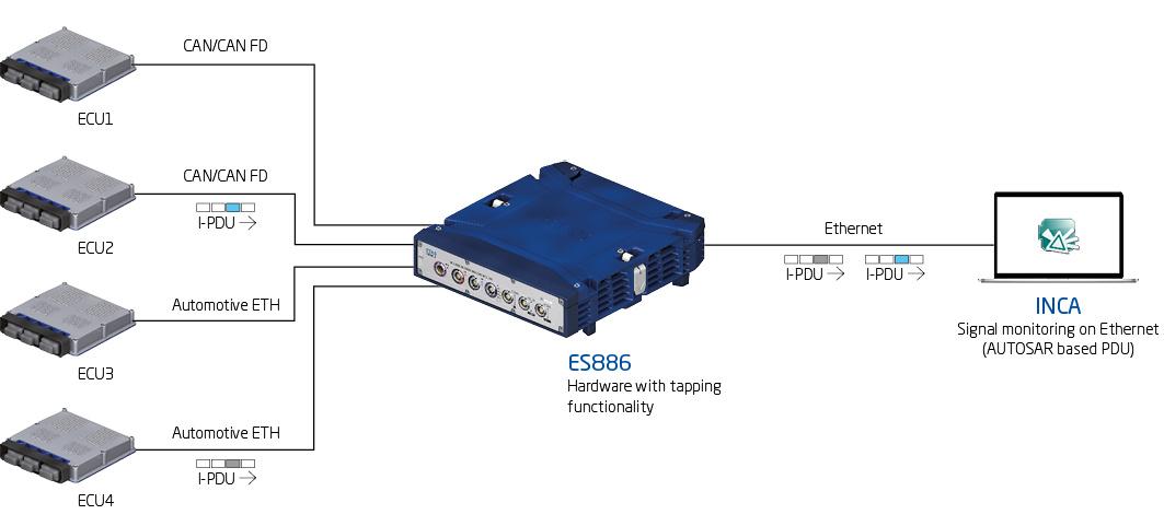
As of INCA 7.2 SP13, the display of AUTOSAR COM based PDU (Protocol Data Unit) messages that are exchanged between two controllers, is possible via the software for Automotive Ethernet. The ETAS ES886 measurement hardware provides the necessary TAP (Test Access Point) functionality. It is used in order to be able to measure Automotive Ethernet based PDU messages in INCA. Meanwhile, both controllers can essentially continue to communicate with each other. UDP/IP, IPv4, E2E protection and IP fragmentation are supported.
The devices VN5610 and VN5610A are also supported.
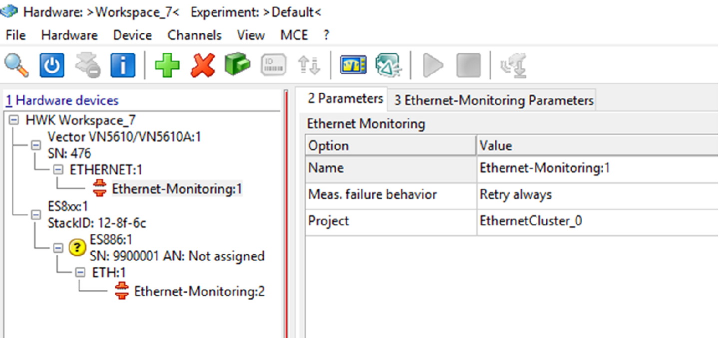
If the ES886 is added in INCA in the hardware selection screen, the Ethernet connection can be selected. Whilst for so-called Tapping two controllers are connected to the Automotive Ethernet ports of ES886, only one is connected for so-called Capturing. Hence, in INCA, the hardware-based connections AE3 and AE4 are assigned to the software-based Port0 and Port1 for Tapping. For Capturing, only the Port AE3 or AE4 that is connected to the device, is selected. The other port is set to "Unused" by the software.
In order for INCA to interpret the PDU messages, AUTOSAR XML files (.arxml) are needed. Ethernet monitoring must not be mixed up with SOME/IP monitoring. SOME/IP support is implemented by a later Service Pack.
XCP
The network protocol now supports IPv6
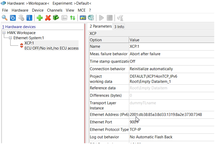
An A2L file can contain either an IPv4 or an IPv6 address for TCP or UDP as communication parameter. INCA now shows either an IPv6 or an IPv4 parameter field in the hardware selection screen for XCP based connections that contains the transmitted parameter with the A2L file or that can be configured manually. Which kind of Internet protocol versions will be shown, is dependent on the A2L description. With the increase of IP-capable devices, IPv6 addresses have become a necessity as they offer a considerably larger address space than IPv4 addresses. More devices can hereby be addressed.
Optional confirmation dialog
No unintended switching between the working and reference page in INCA experiments
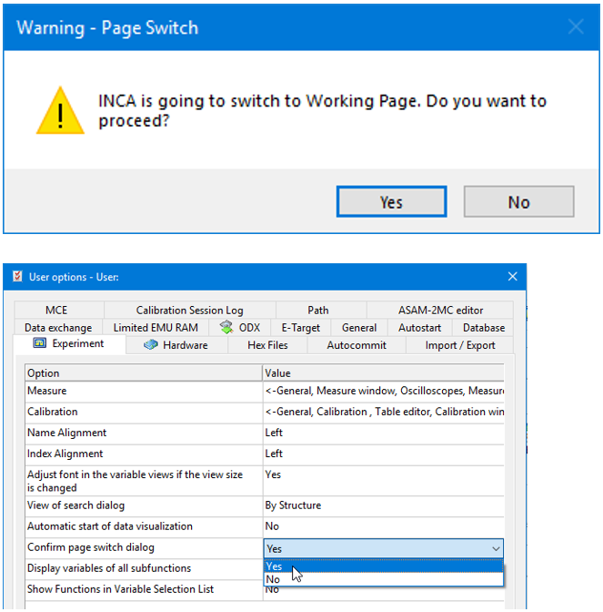
The difference between the working and reference page in INCA can be huge. Since an unintended page switch may damage the engine, INCA now offers an optional confirmation dialog. As this is only necessary when there are critical differences between the working and reference page, the confirmation dialog is initially not active and must be enabled in the INCA user options under the settings for the experiment. Page switches via remote control are always possible, independent of the option setting.
Communication protocols
INCA supports ASAP-V3.0 commands
INCA V7.2 SP13 supports the new ASAP3-V3.0 commands. Commands are now possible that provide information about all rasters and specifically about the available rasters (GET RASTER OVERVIEW and GET MEASUREMENT INFO). Other commands such as PARAMETER FOR VALUE ACQUISITION EV2, GET ONLINE VALUE EV2 and DEFINE RECORDER PARAMETER should be assigned to concrete rasters. Using the aforementioned commands, a label can be assigned to a specific raster. If so far it has been possible to enter the desired scanning rate duration in milliseconds, it is now possible to specify a specific raster thanks to the rise in multi-core processors being used more and more frequently. Furthermore, the command SET FORMAT can now be used to define the format of the adjustment values. This can be a physical value or a controller internal value with no translation method.
VSD
Easy updating of the raster assignment for changed controller software
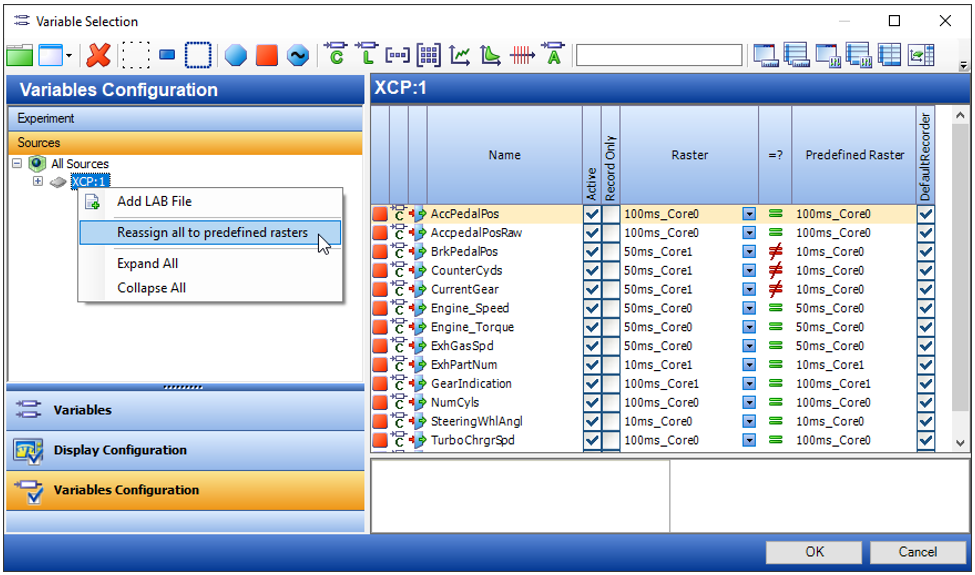
In A2L files, predefined rasters for measurement values can be defined for function variables, so-called labels. INCA can use this information to set up an experiment and save the assignment. With INCA V7.2 SP 13, users can quickly adapt their experiment to the newly defined rasters with an A2L file. If a new version of an A2L file is loaded for this experiment, then INCA can check the predefined rasters and reassign them. This can be beneficial for multi-core controllers where rasters are defined for each core.
If a core or the raster being used has changed, the symbol in INCA shows a crossed out equal sign. A simple right-click, for example on the source or on individual rasters or labels, opens the context menu where the relevant command can be selected to reassign the predefined rasters.
New option
Deleting outdated INCA log files is now possible
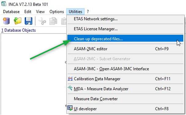
As of version 7.2 SP13, INCA offers the option to delete temporary files and log files. For this purpose, there is now a new menu entry in the INCA menu bar that can be executed. When INCA is closed, specific log files are then deleted to free up any hard drive space that is being used unnecessarily.
Log files and temporary files that INCA has written during installation and usage and that are no longer needed, are deleted. These files were never deleted by INCA, which resulted in an ever increasing number of files.
XCP V1.4
Packed DAQ Lists (DAQ Packed Mode) for optimized controller or ECU interruptions and event measurements
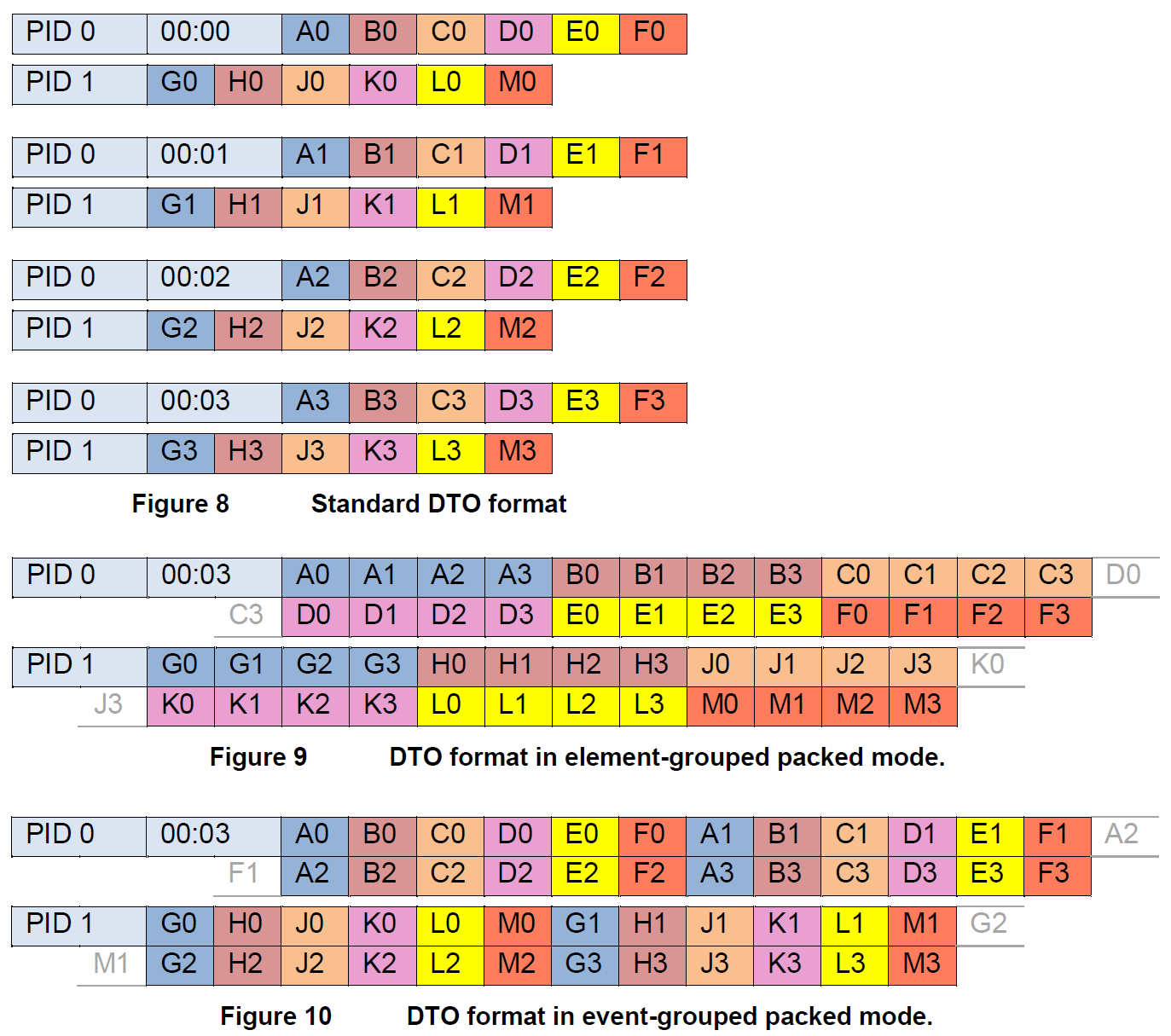
As of version 7.2 SP13, INCA supports so-called Packed DAQ Lists (DAQ Packed Mode) for the network protocol XCP V1.4. This should reduce the number of interrupts of controllers or ECUs and it should be possible to measure events faster. An EVENT cycle time of up to one microsecond is supported. Advantage: More data can be sent where the scan rate or scan frequency is low. In addition to this, data should be reduced (overhead) that is not primarily useful data. Furthermore, the busload can hereby also be optimized. Grouping according to elements (element-grouped) and according to events (event-grouped) is supported.
Experiment
Showing several controllers
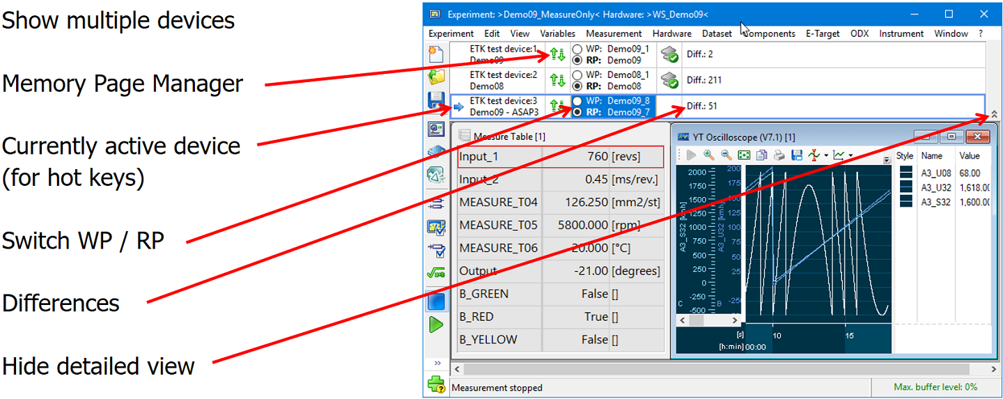
If several controllers are used, information about them can be clearly presented in the INCA Experiment. This is now shown in a table rather than in a combination field, where a controller then had to be selected. Multiple lines can hereby be shown at once. The table can also be expanded and collapsed so that all devices can be shown with their columns.
If you click on the symbol with the pin head, the display remains unchanged for several controllers and does not collapse again. The text in the table view of the controllers used may be shortened in the middle if necessary, but remains visible when you scroll over it with the mouse (tool tip).
Clicking on the button with a green arrow pointing upwards and downwards, pulls up the Memory Page Manager. A blue arrow to the left of the controller designation indicates the controller that is active and ready to receive the valid key combinations. In addition to this, radio buttons are shown for every controller in order to be able to switch between the working and reference page. A column shows the differences per controller.
VN5610A
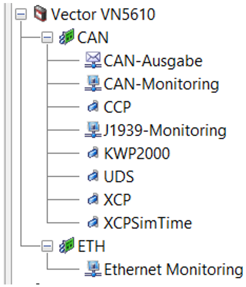
Device connection possible per Automotive Ethernet & BR_XETK
INCA 7.2 SP13 supports the transparent monitoring and recording of Ethernet data streams of the device VN5610A with regards to Automotive Ethernet and BR_XETK. This makes it possible to use the VN5610A for Ethernet monitoring with Capturing and Tapping. The device can also be used as a media converter. In addition to this, two CAN-/CAN-FD ports are supported for XCP, KWP2000, UDS and CAN-monitoring. In order to be able to use the device with INCA, an enable bit has to be ordered for the interface Vector VN5610 USB to Ethernet/CAN/CAN FD. The user then receives an activation key which he can use to enable the device.
License Manager
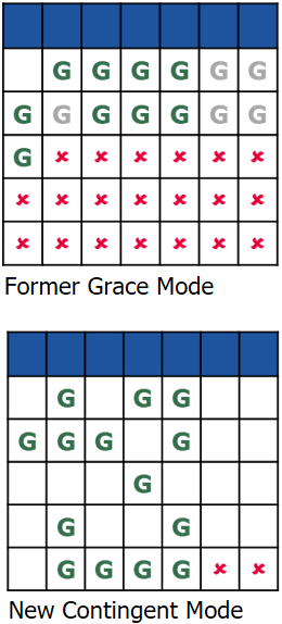
Contingent Mode replaces former Grace Mode
ETAS now supports a Contingent Mode that allows the user to work for several days without a license in a Grace Mode. INCA users are given a contingent of 14 days to use INCA without a license. The contingent of 14 days can be split over single, unconnected days, e.g. when the network is not available. An advantage to users of the new mode is that only the actual usage days count.
The Contingent Mode also supports a refill mechanism that credits some of the used Grace Mode days after a longer period working with a valid license. The new Contingent Mode replaces the former Grace Mode and affects all ETAS applications that use the License Manager with the former Grace Mode
Contingent Mode
Recommendations for ETAS INCA
To ensure that the contingent does not run out on a user's PC, we recommend that ETAS INCA ensures there are enough floating licenses for parallel usage. Furthermore, do not forget to borrow licenses before disconnecting from the network. An optional recommendation is to activate the so-called Auto Borrow mechanism when installing INCA. Furthermore, monitor the remaining user contingent days of Grace Mode. These are shown when INCA is started in Contingent Mode. If the contingent of Grace Mode comes to an end unexpectedly, please contact the ETAS Support. The Support Team can reactivate the contingent in emergency cases.
INCA-SIP
Use of workspace variables in INCA experiments
With INCA 7.2 SP13, users can display MATLAB® workspace variables in INCA and calibrate them. This allows variables to be inserted either directly into the model or as a workspace. It is now possible to access variables that are present in the workspace.
Support for data dictionaries
INCA-SIP users can now access data stored in the data dictionaries. Data dictionaries are permanent directories of model-relevant data, but they offer more potential uses than typical workspace variables. Data dictionaries can, for instance, be stored in external files.
Displaying measurement variables of referenced models
In the case of models referenced in Simulink®, additional measured values can now be displayed in INCA alongside calibration parameters with the help of INCA-SIP. Thanks to this new read functionality, the user now has the option – like in Simulink® – to define which additional measured values should be displayed.
Basic support for Stateflow® blocks
Stateflow® provides model logic and decision logic based on functional state machine diagrams and flow diagrams and is often used in conjunction with Simulink®. With INCA 7.2 SP13, INCA-SIP supports the basic functionality of Stateflow® blocks, which are used in Simulink® models.